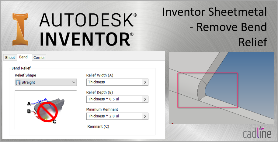
Relief size allows you to input a value to change the size of the corner relief of the selected feature from the default which is defined in the sheet metal style using the named parameter.
Inventor sheet metal corner relief.
How the corner relief on a flat blank of aluminum of a given thickness differs from the corner relief for stainless steel of a different thickness is determined by the options and values defined.
That way you have a dedicated style for each thickness of material and can control relief shapes and bend rads per thickness.
I also need the following info from your sheet metal style settings.
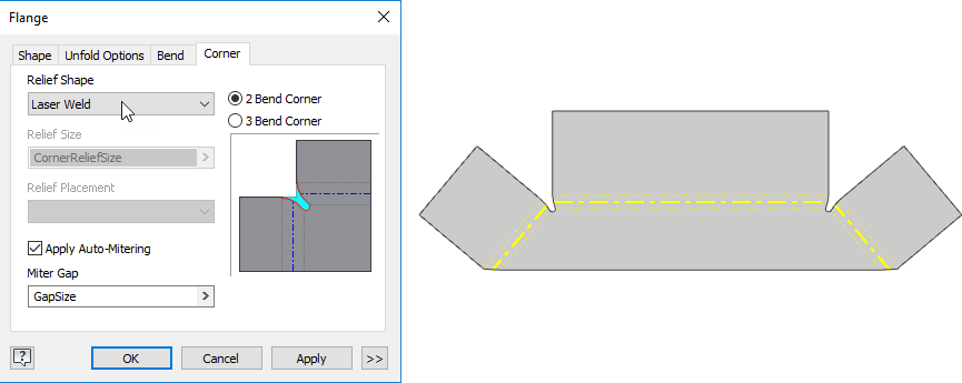
You can edit sheet metal corners override their default style settings and apply auto mitering.
Then added corner seams between the long and sides to set and equal gap but this pulls the corner style from the sheet metal defaults.
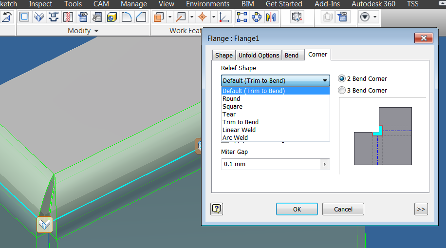
Edit corners in sheet metal features the corner edit dialog box lets you can specify an overlap type overlap gap relief type and relief size that differ from your sheet metal style.
The other options on the flange commandbar include the material side which determines whether the inside or outside of the part is flush with the edge and the measure point which determines whether the flange height is measured from the inside face or the outside face.
On the corner tab relief shape.
Cad cam 4 you 7 238 views.
Apply auto mitering enables automatic material extension between adjacent flange edges during creation or edit of at least two flange edges during a single operation where bend angle.
Also the relief size.
But i have the 3 flanges 2 on the sides and a long one in the back.
Enjoy the videos and music you love upload original content and share it all with friends family and the world on youtube.
If you let me have this i ll see what can be done for it.
You can only specify arc weld replacement in a 2 bend corner.
The automatic corner relief function is also possible for rounded bending zones.
Which inventor are you using.
2019 you can also override default parameters apply auto mitering and specify 2 or 3 bend corners.
Ie a flat sheet with 2 bend plates meeting in the corner.
Inventor is delivered with a pre defined sheet metal rule called.
Synchronous sheet metal is not new but this to me shows that those guys were paying attention when they did add this function.
To try to help you and your business.
Control panel drawing inventor 3d sheet metal for fabrication folded and unfolded in hindi duration.
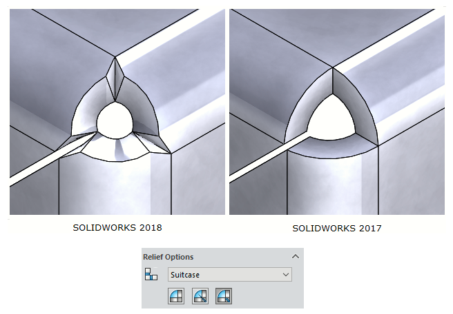
Corner relief this is a limitation.